Up to now we have been working in “Real Mode” or “Compatibility Mode”. This is a very limited mode which the processor initially boots into. It executes 16 bit instructions and registers, can only address 1Mb of RAM, and has no memory protection.
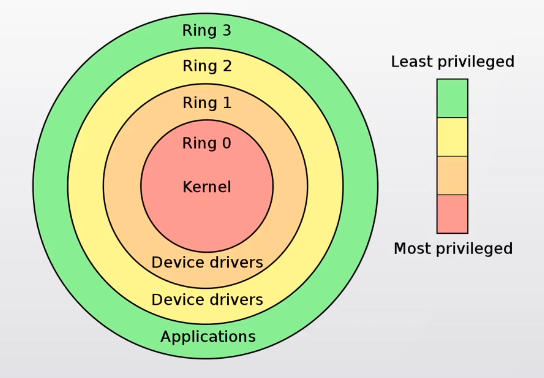
Our next step will be to change into “Protected Mode”. We move to 32bit instructions and registers, and have 4Gb address space. Most importantly it significantly changes the memory model, and protects that memory, limiting how programs can access memory and hardware. Ring 0 is the most privileged, and is where the kernel operates. There are few limits imposed here. You put the processor into Ring 3 when running user applications, limiting them to changing memory in their own ‘block’, preventing them from accessing hardware directly, and limiting the instructions they can run, such as IO.
User programs communicate with the kernel by causing an interrupt. The interrupt will pass control to the kernel, which will switch back to Ring 0, do what it has to do, then pass control back to the user application after switching back to Ring 3.
In Real Mode, our memory scheme was the Segmentation Model, using the 16bit segment registers to address memory. Protected Mode uses the Paging Model. The paging model is an abstraction on top of physical memory. You work with ‘virtual’ blocks (pages) of memory that map back to different physical locations in RAM. As a result, different programs can ‘believe’ they are loaded at the same address, so they don’t need to think about where other programs are, because they can’t see or access them. Programs are effectively sandboxed to the memory space that the kernel has assigned them.1 1 Any virtual and physical address need to be divisible by 4,096, which is the basic block size.
We also switching from using segment registers to selector registers for addressing memory. Each selector points to a data structure which describes a memory range and the permissions of that range.
We will use the instructions per the OSDev wiki. The
instruction called lgdt is the critical one. This stands
for “Load Global Descriptor Table”.
cli ; disable interrupts
lgdt [gdtr] ; load GDT register with start address of Global Descriptor Table
mov eax, cr0
or al, 1 ; set PE (Protection Enable) bit in CR0 (Control Register 0)
mov cr0, eax
; Perform far jump to selector 08h (offset into GDT, pointing at a 32bit PM code segment descriptor)
; to load CS with proper PM32 descriptor)
jmp 08h:PModeMain
PModeMain:
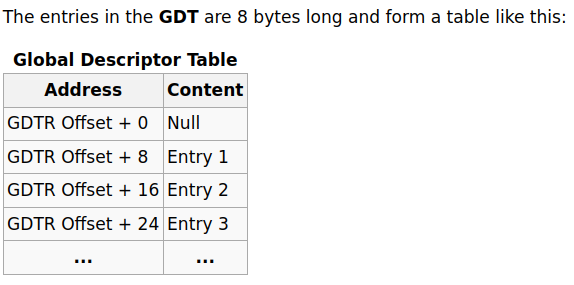
; load DS, ES, FS, GS, SS, ESPThe Global
Descriptor Table (GDT) contains entries telling the CPU about
memory Segments. The GDT contains pointers to GDT Entries - the
descriptors themselves. The GDT entries describe the memory and the
access rights. While we will need to set this up, we’re going gloss over
a lot of the detail and use default values, because our kernel is going
to use paging, meaning after a point this will no longer be relevant.
The following is the relevant code, which starts after the
start block.
.load_protected:
    cli
    lgdt[gdt_descriptor]
    mov eax, cr0
    or eax, 0x1
    mov cr0, eax
    jmp CODE_SEG:load32 ; we'll define what CODE_SEG is later

gdt_start:
gdt_null:
    dd 0x0
    dd 0x0

; offset 0x8
gdt_code:     ; CS should point to this
    dw 0xFFFF ; Seg Limit first 0-15 bits
    dw 0      ; base first 0-15 bits
    db 0      ; base 16-23 bits
    db 0x9a   ; access byte
    db 11001111b ; hi+lo 4bit flags
    db 0

; offset 0x10
gdt_data:     ; DS/SS/ES/FS/GS
    dw 0xFFFF ; Seg Limit first 0-15 bits
    dw 0      ; base first 0-15 bits
    db 0      ; base 16-23 bits
    db 0x92   ; access byte
    db 11001111b ; hi+lo 4bit flags
    db 0

gdt_end:
gdt_descriptor:
    dw gdt_end - gdt_start-1
    dd gdt_start
Starting from the gdt_start label: The first entry in
the GDT is NULL. The two dd 0x0 creates a
“null segment” 8 bytes/64bits of nulls. From gdt_code we
create our entry, which is the selector which will link to our Code
Segment. Again, don’t worry too much about what these are for now,
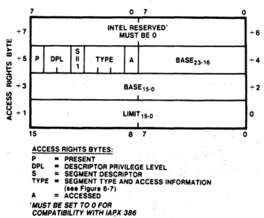
they are basically default values. The access byte is a bitmask
containing flags. We put in another entry, gdt_data, which
will be linked to all of our other Segments: Data, Stack, Extra, and two
General Segments, G and F. It’s identical with the exception of the
access byte.
Next we provide some descriptors, firstly the size of our GDT, and
secondly the location of the GDT in the program. These will be used by
lgdt. Finally we set up our load_protected
block. This loads the GDT, defaults the control register
cr0 to 0x1 if null, and jumps to
CODE_SEG:load32.
Before actually writing load32 we need to do a couple of
things. One thing we need to change is our origin, which is our offset.
Currently this is set to 0. Previously this was fine, since we jumped
straight to where the code was being loaded in memory: segment
0x7c0. Now, however, our GDT descriptor will point to
0:gdt_descriptor. So change the ORG to 0x7C00.
A couple of other things will need to change in sympathy. We also want
to define CODE_SEG and DATA_SEG, which will
point to entries in our GDT.
ORG 0x7C00 ; changed from 0
BITS 16

CODE_SEG equ gdt_code - gdt_start ; defines CODE_SEG as the offset from GDT start
DATA_SEG equ gdt_data - gdt_start ; same for DATA_SEG

jmp 0:start ; absolute 0x7c0 (start is at 0x7c05)

; since our origin is now 0x7c00, our segments need to 0x00 (???)
start:
    cli
    mov ax, 0x00
    mov ds, ax
    mov es, ax
    mov ss, ax
    mov sp, 0x7c00
    sti
Now for load32. First, change into 32bit mode. Here we
mostly just setup registers (Code segment register is already set by the
origin?). We also point the stack frame/stack pointer registers
ebp and esp.
[BITS 32]
load32:
    mov ax, DATA_SEG
    mov ds, ax
    mov es, ax
    mov fs, ax
    mov gs, ax
    mov ss, ax
    mov ebp, 0x00200000
    mov esp, ebp
jmp $We can test this with the GNU Debugger, gdp. You might need to install it.
$ gdb
(gdb) target remote | qemu-system-x86_64 -hda ./bin/boot.bin -S -gbd stdio
Enter c to continue, your qemu should boot.
Send a SIGINT with Ctrl+c. You should see:
Program received signal SIGINT, Interrupt. 0x0000000000007c5b in ?? ().
This indicates the program is currently executing at RAM location
0x7c5b. If you type layout asm, you can see
the value in memory at 0x7c5b, and see that it is the
infinite jump jmp $ at the end of our load routine. You can
also type info registers and see that your code segment
register is set to 8, and the other ones to 16 (0x10).
You are now in protected / 32 bit mode! Note that this means you can’t talk to the BIOS directly anymore.
The A20 Line is
necessary to access the 21st bit (bit 20) of any 32bit/4byte block. The
reason that this is disabled by default is some obscure compatibility
issue, which isn’t important. You can read more about it at the above
link if you want. The method for doing this is very simple: 3
instructions in the load32 section. The in and
out instructions read and write to processor bus
respectively. Test this with gdb.
    ;snip
    mov esp, ebp

    ; enable A20 line
    in al, 0x92
    or al, 2
    out 0x92, al

    jmp $