This is based on a course which guides the reader through the development of a full OS kernel, from a Hello World Bootloader to a multitasking kernel with a FAT16 file system. The first 11 lessons are available for free on YouTube
Memory is a piece of hardware that allows computers to store information. Programs can read and write to Random Access Memory (RAM). It’s only used for temporary storage, such as for variable storage of the programs you write. RAM is wiped when you shut down the computer. Read Only Memory (ROM) does not vanish when you shut down the computer. But as the name suggests, you can’t write to it. In a home PC, the BIOS program is stored in ROM.
Memory is generally accessed in a linear fashion. The data is stored in order. The way your processor accesses memory abstracts this.
The boot process has three steps:
0x7C00
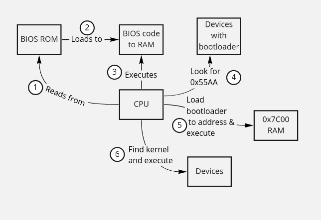
When the computer is switched on, the CPU will read from the BIOS ROM and start executing instructions it finds there. The BIOS usually loads itself into RAM for performance reasons and will continue to execute from there. The BIOS also identifies and initializes the computer’s hardware, such as disk drivers.
The final thing the BIOS does is try to find a Bootloader. It
searches all available storage mediums - USB drives, hard disks - for
the magic boot signature 0x55AA. It will look in the last
bytes of the first
sector2
2 A
sector is a block of storage. For example, a hard disk is made up of 512
byte sectors. The BIOS will look in the byte addresses 511 and 512 of
the sector.
and if the signature is found, it will load that sector into address
0x7C00, and the CPU will start to execute from that
address.
When a computer first boots, it does so in “Real Mode”. This is a very limited ‘compatibility’ mode, with access to only 1Mb of memory, and it can only execute 16 bit code. The Bootloader is a small program whose job is to put the computer into “Protected Mode”, which allows 32 bit code and access to 4Gb of memory, and then to load the kernel of an operating system.
The BIOS contains routines that the bootloader uses to boot the kernel. The interfaces of BIOS routines are generic and standardized across manufacturers.
All development will be done on Ubuntu Linux. First, make sure your repositories are up to date. Then, install nasm4 4 NASM is the “Netwide Assembler”, and assembler for the x86 CPU architecture, compatible with nearly every modern platform. https://nasm.us . Finally, we will use the QEmu emulator to run our bootloader and kernel. Test that it runs using the below commands. A new window will pop up, but since there are no disks attached it won’t be able to boot.
sudo apt update
sudo apt install nasm

sudo apt install qemu-system-x86
qemu-system-x86_64This is a short refresher on what assembly language is. Or, for me, basically an introduction to it, since I’ve never written it before.
Your processor has an instruction set, or machine codes. Assembly language gets passed through an assembler, and machine codes your processor understands come out the other side. Use Emu8086 to easily test assembly programs.5 5 For linux users, it works fine with Wine.
Write the following program in your emulator:
mov ah, 0eh
mov al, 'A'
int 10h
This is a program that outputs ‘A’ to the screen.
mov X Y moves data Y to
register6
6 A
register is a storage location in the processor.
X. ah (“Accumulator High”) and al
(“Accumulator Low”) are registers storing one byte. So here we move
0eh7
7
0e in hex, 14 in decimal
into ah, and the character ‘A’ (65) into al.
int X means “interrupt with code X”. The code
10h outputs things to the
screen8
8
Specifically, 10h is a BIOS routine: A function that is defined
in the BIOs, and can only be used in compatibility mode.
So we have a program that outputs a character to a screen. Now we need to output multiple characters. Here is our next program.
jmp main

message: db 'Hello World!', 0

print:
    mov ah, 0eh
._loop:
    lodsb
    cmp al, 0
    je .done
    int 10h
    jmp ._loop
.done:
    ret

main:
    mov si, message
    call print
The first thing to point out is that assembly always executes
top-to-bottom unless you specifically tell it to jump to somewhere else.
This is done with labels. These are the words that end with
colons, like main:. For example print is a
subroutine, and when it is called with call print, the
program will start executing at this point.
The line message: db 'Hello World!', 0, puts a block of
data representing the bytes ‘Hello World!’ at the starting memory
location (db mean data bytes I think). The zero at the end
is the ‘null’ terminator. We have to put jmp main above
that, otherwise the processor will try to execute the data, which it
will think are instructions.
Main has been changed to move register si (“Source
index”, used as a data pointer) to the address of our message. The it
calls print. The print subroutine is an
elaboration on the “print character” code. The first instructions are
the lodsb (“load string byte”), which loads the character
at si into al, and increments si,
moving it to the address of the next character. cmp
“compares” the value in al to 0, and if it is 0 (meaning we
are at the end of the string), it jumps to done and returns. Otherwise
it jumps back to the loop label
Next we will turn our “hello world” program into a bootloader. That is, the program will be loaded by the BIOS and, when we boot the machine, it will show “Hello World!” on the screen.
Create a new folder / project PeachOS. Make a new file boot.asm, and add the following code:
ORG 0x7c00
BITS 16

start:
    mov si, message
    call print
    jmp $

print:
    mov bx, 0
.loop:
    lodsb
    cmp al, 0
    je .done
    call print_char
    jmp .loop
.done:
    ret

print_char:
    mov ah, 0eh
    int 0x10
    ret

message: db 'Hello World!', 0

times 510-($ - $$) db 0 ; Pad to 510th byte
dw 0xAA55 ; dw=define word. Puts bootloader signal
This is very similar to our non-bootloader code. There are a couple
of organizational changes (print_char has been extracted
into a subroutine, things have been moved around a bit), and a couple
that are required to make this function as a bootloader.
ORG 0x7C00 sets the ‘origin’ or ‘starting location’ where
your program is loaded into memory. Bootloaders are always loaded to
0x7C00. BITS 16 tells the processor that it
should interpret the program in 16bit mode (“Real Mode”, or
“Compatibility Mode”). The last two lines pad out the program with
zeros, and then put the value 0x55AA (the ‘signal’ that
this is a bootloader) to the last 2 bytes of the
sector.9
9 Note
that we say 0xAA55 in the code. This is because bytes are
loaded ‘backwards’, with 55h being loaded first.
Assemble your bootloader and boot it with
nasm -f bin ./boot.asm -o ./boot.bin
ndisasm boot.bin #look at the machine code
qemu-system-x86_64 -hda ./boot.binWe have seen that the pointer registers in the processor are 2 bytes. That means your instruction pointer for example, which is 2 bytes, can point to memory locations (addresses) between bytes number 0 and (2^16) 65,535. However we’ve seen that in real mode, the processor has access to 1Mb of memory, or 1,048,576 bytes. How can we get our pointers to point to values above 65,535?
The answer is the Segmentation Memory Model. Memory is
accessed by the combination of a segment and an
offset. This is what the segment registers are for.
There are 4 in the 8086: Code segment cs, Data segment
ds, Extra segment es and Stack segment
ss. The segment and offset can be combined to calculate the
absolute offset (the actual memory location in RAM) by
multiplying the segment by 16 (A left shift in hex) and adding the
offset10
10
Note that ORG or origin is also factored in. .
For example, if your segment is 0x7C0 and your offset
(instruction pointer) and origin are both zero. The absolute memory
address your program will start executing at is
0x7C0 * 16 = 0x7C00. If your offset is 0xFF,
the absolute address will be 0x7CFF. If segment is
0xF000 and offset is 0xFFFF, the absolute
memory address is FFFFF, or 1,048,575. This is how you
address a megabyte of memory using two 16bit registers. Note that this
model means that you can get to an address in multiple ways. For
example, if your segment is 0x7CF and offset is
0x0F, the absolute address is also 0x7CFF.
Different instructions in the processor’s instruction set use
different combinations of registers to determine which absolute address
to look at. For example, lodsb which we’ve already seen
uses the data segment register and the source index register
(shorthanded to ds:si).
Segment registers can be used in source using the following convention:
mov byte al, [es:32]This will move the byte located in es:32 into
al.
One thing we need to do with our bootloader is to make sure all the
segment registered are initialized to the values we want. The BIOS and
interrupts can sometimes mess with these. Change the origin to 0. Give a
jmp instruction to 0x7c0, which changes the
instruction pointer. Change data and extra segments to
0x7c0. Change the stack segment to 0x00 and
the stack pointer to 0x7c00.
ORG 0
BITS 16

jmp 0x7c0:start

start:
    cli ; clear interrupts
    mov ax, 0x7C0
    mov ds, ax
    mov es, ax
    mov ax, 0x00
    mov ss, ax
    mov sp, 0x7c00
    sti ; enables interrupts again
    mov si, message
    call print
To reiterate what our code is now doing:
0x55AA in
our binary ‘hard drive’0x7c00, and starts executing0x7c0:start11.